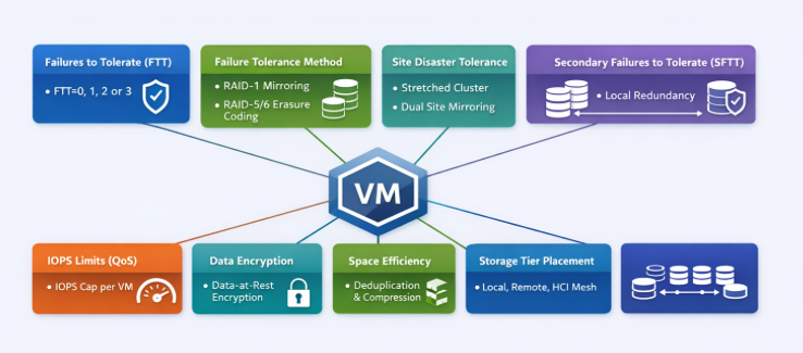
Storage Policy–Based Management (SPBM) is the backbone of how VMware vSAN delivers predictable, workload‑aligned outcomes. Instead of carving LUNs or managing fixed RAID groups the old-fashioned way, policies define the storage behavior of each VM and each VMDK—granular, dynamic, and automated. This approach simplifies operations, enables workload‑specific tuning, and eliminates the rigidity of traditional storage constructs.
Below, we’ll explore the key vSAN storage policy components, along with their advantages and disadvantages, from an architectural design perspective.
Primary Level of Failures to Tolerate (PFTT)
The Primary Level of Failures to Tolerate (FTT) dictates how many concurrent host, disk, or fault domain failures a VM object can survive. Values range from 0 to 3 depending on cluster size and hardware availability.
How it works
- FTT=0: No redundancy; best for non‑critical or ephemeral workloads.
- FTT=1: One mirror or parity protection instance.
- FTT=2 or 3: Increasingly higher tolerance, requiring more hosts and capacity.
Advantages
- Granular protection that can be tailored per VM.
- Easy to modify without storage migration—vSAN automatically reconfigures components.
Disadvantages
- Higher FTT increases storage consumption significantly (e.g., FTT=1 mirroring effectively doubles capacity).
- Higher FTT requires larger clusters and more fault domains.
Failure Tolerance Method (FTM): Mirroring vs. Erasure Coding
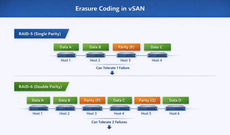
vSAN supports two primary protection mechanisms under FTM, Mirroring (RAID1) or Erasure Coding (RAID5/6). What are the differences:
Mirroring is a data‑protection technique where full, identical copies of data are stored across multiple hosts or storage devices. In vSAN, this is implemented through RAID‑1 (Mirroring), the performance‑optimized protection model. With FTT=1, vSAN stores two full copies across different hosts. With FTT=2, vSAN stores three full copies, and so on
Erasure coding is a data‑protection technique that breaks data into chunks, adds parity information, and distributes those chunks across multiple hosts or storage devices. In vSAN, it is implemented through RAID‑5 (single parity) and RAID‑6 (double parity) policies, both of which provide storage efficiency by using parity instead of full mirroring.
Comparison of the three options, Mirror or two types of Erasure Coding:
| Attribute | RAID‑1 (Mirroring) | RAID‑5 (Single‑Parity Erasure Coding) | RAID‑6 (Double‑Parity Erasure Coding) |
| Protection Method | Full data mirroring across replicas. | Data striping with one parity block per stripe. | Data striping with two parity blocks per stripe. |
| Minimum Host Requirement (vSAN) | Depends on FTT: 2 hosts for FTT=1, 3+ for higher. | Minimum 4 hosts. | Minimum 6 hosts. |
| Failures Tolerated | Equal to FTT value (e.g., FTT=1 tolerates 1 mirror/site failure). | Tolerates 1 failure (single parity). | Tolerates 2 failures (dual parity). |
| Capacity Overhead | Very high: 2× for FTT=1, 3× for FTT=2. | Moderate: ~1.33× overhead in typical RAID‑5 layout. | Efficient: ~1.5× overhead for RAID‑6. |
| Write Performance | Highest—no parity calculation; synchronous writes to mirrors. | Lower—requires parity computation (read‑modify‑write). | Lower still—two parity calculations required. |
| Read Performance | High—reads can be serviced from any mirror. | Good—reads use data stripes, parity only for reconstruction. | Good—similar to RAID‑5, with additional parity available. |
| Best For | Latency‑sensitive, high‑performance workloads (databases, transactional systems). | Capacity‑sensitive workloads with moderate I/O (file services, general VMs). | Large clusters needing strong redundancy with good capacity efficiency (archive, analytics). |
| Drawbacks | Extremely high capacity consumption. | Higher write latency and CPU cost due to single‑parity overhead. | Highest parity overhead; worst write performance of the three. |
Site Disaster Tolerance (SDT)
Mirror:
vSAN Site Disaster Tolerance with mirroring (typically using a Stretched Cluster configuration) works by creating a full replica of data across two geographically separated, active sites, ensuring zero-downtime failover. Using RAID-1 (Mirroring) for site-level protection, a complete copy of the virtual machine is maintained at both the “Preferred” and “Secondary” sites.
How it Works:
- Active-Active Sites: Both sites are active. A write to a virtual machine in the Preferred site is synchronously written to the Secondary site across an Inter-Switch Link (ISL).
- Witness Host: A third, independent site hosts a vSAN Witness Host, which does not store data but acts as a tie-breaker to prevent “split-brain” scenarios and maintain cluster quorum.
- Site Mirroring (RAID-1): In a 2-site configuration with Site Mirroring, the data is mirrored between Site A and Site B.
- Local Protection: In addition to site-level mirroring, local data redundancy (RAID-1 or RAID-5/6) can be configured within each site to handle local disk/host failures.
Erasure Coding:
vSAN site disaster tolerance with erasure coding (RAID 5/6) works by splitting data into chunks, creating parity, and distributing them across sites, requiring no full mirror copy. It uses a 3-site setup (Site A, Site B, Witness) to calculate parity on the fly, offering space efficiency over traditional RAID-1 mirroring
Key Details on Erasure Coding in Stretched Clusters:
- Mechanism: Instead of mirroring, vSAN uses RAID 5 or 6 (Erasure Coding) to break data into fragments, calculates parity data, and distributes them across sites to tolerate a full site failure.
- Site Configuration: A minimum of 3 sites (Site A, Site B, and a Witness host) is required.
- Space Efficiency: RAID 5 provides a 1.33x capacity overhead (compared to 2x or 3x for mirroring) to achieve a 1-site failure tolerance, while RAID 6 provides higher protection with less, typically around 1.5x, but requires more hosts.
- Requirements: Requires at least 4 nodes in each site (Availability Zone) for RAID 5, and 6 nodes for RAID 6.
- Performance vs. Capacity: While erasure coding is more space-efficient, it requires more CPU overhead for parity calculations, making it better for write-heavy workloads that need to save capacity
Secondary Failures to Tolerate (SFTT)
When combining stretched‑cluster protection with intra‑site protection, SFTT defines the number of local failures that can be tolerated within each site.
Advantages
- Enables extremely robust protection across and within sites.
- Critical for mission‑critical workloads requiring multi‑layered resiliency.
Disadvantages
- High capacity overhead.
- Requires large host counts due to compound failure models (e.g., site + local host failures).
Comparison Table
| SDT + SFTT Scenario | Site Protection | Local Protection | Storage Overhead | Typical Use Case |
| SDT + SFTT=0 | Yes | No | Lowest | Basic DR setups |
| SDT + SFTT=1 | Yes | 1 failure (RAID‑1/5) | Medium | General workloads |
| SDT + SFTT=2 | Yes | 2 failures (RAID‑6) | High | Mission‑critical, large clusters |
| SDT + EC Hybrid | Yes | EC in each site | Moderate | Capacity‑efficient DR clusters |
Striping (Stripe Width)
Stripe width controls the number of capacity devices an object is distributed across, increasing the potential bandwidth consumption. Listed as “Number of disk stripes per object.”
Advantages
- Increases parallelism; potentially boosts performance.
- Useful for very large or sequential workloads.
Disadvantages
- Consumes additional components, which may stress component count limits.
- No guarantee of improved performance unless workload is truly parallel.
In the ESA, the stripe width has a limited impact because the architecture and the LSOM layer are optimized for NVMe speed and parallelism.
IOPS Limit for Object (QoS Controls)
Policies can enforce IOPS limits on a per‑object basis, allowing architects to throttle noisy neighbors or to create performance tiering within the vSAN infrastructure.
Advantages
- Enforces fairness across VMs.
- Prevents performance degradation in mixed‑tenant environments.
Disadvantages
- Misconfigured limits can bottleneck critical workloads.
- Requires monitoring to ensure effective placement.
Deduplication/Compression or None
vSAN all‑flash deployments can leverage dedupe/compression at the cluster level, but storage policies can still influence how space efficiency interacts with tiers and remote storage (e.g., via HCI Mesh).
Advantages
- Major savings for compressible/dedup‑friendly workloads.
- Great fit for VDI or homogeneous datasets.
Disadvantages
Not optimal for encrypted or highly unique workloads.
DDC vs None Across Mirroring & Erasure Coding
| Feature | RAID‑1 + DDC | RAID‑1 + None | RAID‑5/6 + DDC | RAID‑5/6 + None |
| Performance | Medium | Best | Lowest | Medium‑Low |
| Capacity Efficiency | Medium | Poor | Best | Good |
| CPU Overhead | Medium‑High | Lowest | Highest | Medium |
| Ideal For | VDI, repetitive OS disks | Latency‑sensitive DBs | Big data, logs, large pools | General workloads on large clusters |
| Risk | DDC overhead | High capacity cost | Highest latency path | Parity overhead only |
Conclusion
vSAN storage policies are more than configuration items—they’re architectural contracts that describe the exact performance, resiliency, efficiency, and behavior expectations for every workload. SPBM abstracts away the limitations of traditional arrays and empowers architects to deliver bespoke storage outcomes per VM, per disk, and at any time without disruptive migrations.
When properly designed, vSAN policies become a powerful tool to balance capacity, performance, and SLAs across diverse workloads. The key is understanding the trade‑offs and selecting policy combinations that align precisely with application intent and cluster capabilities.